_White_Background_square_1920px.png?width=256&height=96&name=FLEETWATCH%20Fleet%20Information%20Technology%20by%20S%26A%20Systems%2c%20Inc%20(06_28_2021)_White_Background_square_1920px.png)
Replacing the RIH3000R with a Spare
Download the PDF: Replace the RIH with Spare RIH
A step-by-step procedure for swapping a Fleetwatch RIH 3000R Remote Island Head for a spare unit at the JB20 junction box.
Equipment: RIH 3000R | Junction box: JB20 | Steps: 8 | Estimated time: 15–20 min
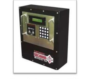
Figure 1: Fleetwatch RIH 3000R
What you're replacing
The RIH 3000R is the keypad/display unit (Remote Island Head) that talks to the Fleetwatch server. If it fails, it is swapped for a spare unit mounted at the same stand or wall bracket — no rewiring required, just three military connectors and four mounting nuts.
Before you begin: De-energize the RIH before disconnecting anything. Step 1 walks you through locking out power at breaker CB1 inside the JB20 junction box — do not skip it, and do not force any connector.
Procedure at a glance
- Phase 1 · Steps 1–4 — Power down & remove: Lock out power at CB1, disconnect the old RIH, and free it from its mount.
- Phase 2 · Steps 5–6 — Install & power up: Mount the spare, reconnect it, and restore power at CB1.
- Phase 3 · Steps 7–8 — Initialize & verify: Key-switch reset, press RESET, and confirm the unit is talking to the server.
Phase 1 — Power Down & Remove
Step 1: Lock out power at the junction box
Unlock the JB20 junction box and turn off power to the RIH by switching breaker CB1 to the OFF position. Confirm the unit is fully de-energized before continuing.

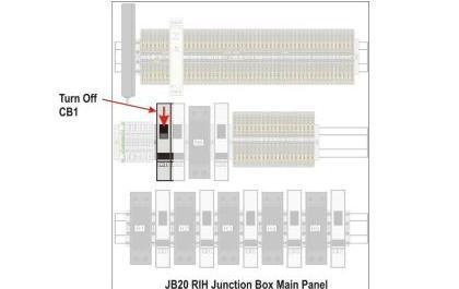
Figure 2: Fleetwatch JB20 junction box | Figure 3: Turn CB1 off on the JB20 main panel
Step 2: Disconnect the military connectors
Unscrew the three military connectors from the back of the RIH.
Step 3: Free the unit from its mount
Remove the four nuts holding the RIH to its stand or wall bracket.
Step 4: Mount the spare
Mount the spare RIH to the same bracket or stand.
Phase 2 — Install & Power Up
Step 5: Reconnect the military connectors
Reconnect the three military connectors to the new RIH.
Hand-tighten the connectors. Do not overtighten — overtightening can damage the connectors.
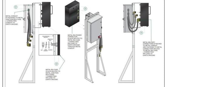
Figure 4: Earth-ground path — the metal RIH case, conduit, and connectors all bond together through the stand or wall bracket. Keep these metal-to-metal connections clean and secure.
Step 6: Restore power
Turn power back on to the RIH using breaker CB1.
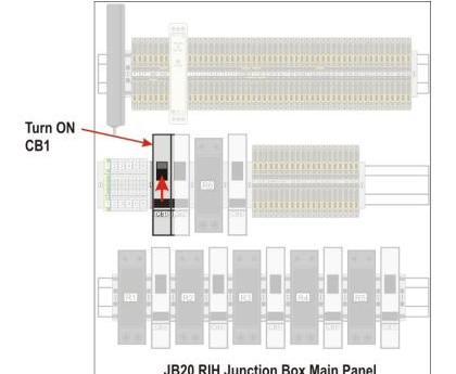
Figure 5: Turn CB1 back on at the JB20 main panel
Phase 3 — Initialize & Verify
Step 7: Reset with the Auto/Manual key
Using the Auto/Manual key, perform a reset by turning the Start key switch to the right, then let it spring back to the normal position. This tells the RIH to talk to the server and brings up the correct prompts. If needed, call S&A Systems to initialize the RIH remotely.
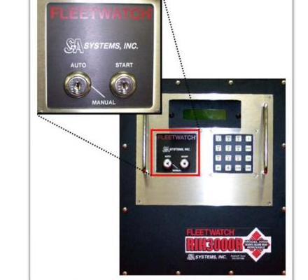
Figure 6: Turn the key switch to initialize the RIH and display the correct prompts
Step 8: Press RESET
Press RESET on the keypad to complete the process and confirm the correct prompts are displayed.
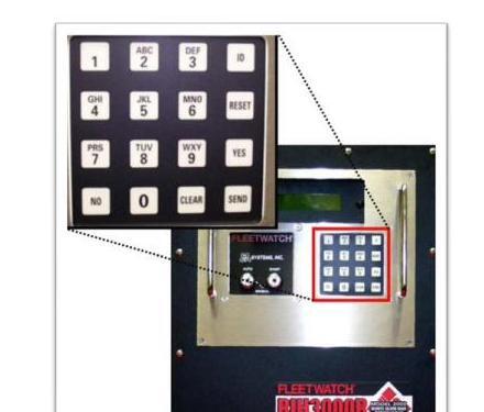
Figure 7: Press RESET on the keypad to finish
Need a hand?
For system validation, or if anything doesn't look right after Step 8, call S&A Systems, Inc. at (972) 722-1009 x32 and ask for system validation.
- When removing and replacing the connectors on the back of the RIH, only hand-tighten the connectors. Do not use a wrench to tighten the connectors.