_White_Background_square_1920px.png?width=256&height=96&name=FLEETWATCH%20Fleet%20Information%20Technology%20by%20S%26A%20Systems%2c%20Inc%20(06_28_2021)_White_Background_square_1920px.png)
S&A Systems, Inc. · Fleetwatch Field Service Procedure RIH3000R Keypad Overlay Replacement
A step-by-step procedure for replacing the keypad overlay assembly on a Fleetwatch RIH 3000R Remote Island Head at the workbench.
Download the PDF: How-to Replace RIH Keypad Overlay
| EquipmentRIH 3000R | AssemblyKeypad Overlay | Steps15 | Est. Time30–45 min |
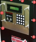 |
Fig 01 — RIH 3000R Keypad Face What You're Replacing
The keypad overlay is the sealed button membrane mounted over the KB circuit board on the RIH 3000R faceplate. Replace it when buttons stick, stop registering, or the seal has failed. The swap happens at a workbench with the front cover removed — the display and motherboard stay wired in place. |
Tools & Supplies Required
- Phillips screwdriver — removes the RIH front cover
- 5/16″ nut-driver, socket, or wrench — removes the keypad assembly
- RTV silicone — reseals the keypad assembly after installation
| Before You Begin | De-energize the RIH before opening the case. Step 1 walks you through locking out power at breaker CB1 in the JB20 junction box — do not skip it. Once the cover is open, watch the display ribbon cable closely: if it comes off the display, it's difficult to realign. |
Procedure at a Glance
| Phase 1 · Steps 1–3 Power Down & Open Lock out CB1, remove the RIH from its mount, and open the front cover. | Phase 2 · Steps 4–6 Access the Keypad Disconnect the display and keypad ribbon cables and note nut/washer orientation. | Phase 3 · Steps 7–11 Swap the Overlay Remove the KB circuit board and old overlay, clean the plate, and set the new one. | Phase 4 · Steps 12–15 Reseal & Test Silicone the seal, reassemble the cover, and test every button. |
Phase 1 — Power Down & Open
| 1 | Lock Out Power at the Junction Box Turn off breaker CB1 in the JB20 electrical box connected to the RIH. Confirm the unit is fully de-energized before continuing. | FIG 02 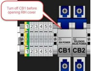 Turn off CB1 to power down the RIH. Turn off CB1 to power down the RIH. |
| 2 | Remove the RIH From Its Mount Remove the cannon plugs from the back of the RIH along with the 4 nuts securing it to the stand or wall bracket, then carry the unit to a workbench. |
| 3 | Open the Front Cover Remove the screws around the RIH cover, then carefully take off the front cover to expose the inside of the faceplate. You may need to gently pry the cover from the bottom of the case. Insert a flathead screwdriver no more than ¼ inch between the cover and case — just enough to pry the seal loose. Forcing it further can damage internal components. Remove the cover slowly and watch the display ribbon cable. Don't let it come off the display — it's difficult to realign. | FIG 03 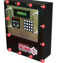 Remove these screws to access the keypad. Remove these screws to access the keypad. |
Phase 2 — Access the Keypad
| 4 | Disconnect the Display Ribbon Cable Disconnect the display ribbon cable from the motherboard after noting where it goes. Do not remove the ribbon cable from the display itself. | FIG 04 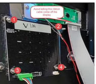 Backside of the keypad assembly. Backside of the keypad assembly. |
| 5 | Disconnect the Keypad Ribbon Cable Disconnect the keypad ribbon cable from the keypad itself. Leave the keypad cable connected to the motherboard — do not disconnect it there. |
| 6 | Note Nut & Washer Orientation Before removing the 4 nuts from the keypad, note the orientation of the washers and nuts. They must go back on exactly the same way for the buttons to depress properly on reassembly. Take photos of the nut and washer stack-up before disassembly — it's the easiest way to get reassembly right. |
Phase 3 — Swap the Overlay
| 7 | Remove the KB Circuit Board Use a 5/16″ tool to remove the 4 nuts holding the KB circuit board. Do not disconnect any wires from the circuit board. |
| 8 | Remove the Old Overlay's Mounting Nuts Use a 5/16″ tool to remove the 4 nuts securing the keypad overlay assembly. |
| 9 | Lift Off the Old Overlay Remove the keypad overlay assembly from the front plate. |
| 10 | Clean the Front Plate Clean any excess silicone from the front plate surface so the new overlay can seat flush. |
| 11 | Set the New Overlay Place the new keypad overlay assembly in position and fasten it tight. |
Phase 4 — Reseal & Test
| 12 | Reseal the Overlay Apply RTV silicone around the keypad overlay assembly to re-establish a waterproof seal. |
| 13 | Reinstall the KB Circuit Board Place the KB circuit board back over the keypad overlay assembly and fasten it tight. |
| 14 | Reinstall the Front Plate Place the RIH front plate back on the RIH case and tighten the Phillips head screws. |
| 15 | Power Up & Test Turn CB1 back on and test each button to confirm they all register correctly. | FIG 05 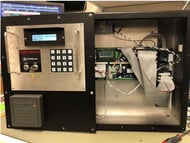 Fully reassembled RIH — this is how the wiring and cover should look whether you're at the bench or back in the field. Fully reassembled RIH — this is how the wiring and cover should look whether you're at the bench or back in the field. |
| Need a Hand? If a button doesn't register after reassembly, or the seal doesn't look right, call S&A Systems, Inc. | (972) 722-1009 x32 Ask for Technical Support |
When you remove the front cover of the RIH, do not let the display ribbon cable come off of the display, as it's often difficult to realign.
Pay special attention to the washers and nuts on the keypad. They need to go back the exact same way so the buttons will work when reassembled.
Last word of caution, use silicone sealant to seal the keypad after reinstalling, especially for any RIH in an outdoor location, or